
“What really makes an instrument musical is that a musician decides to make use of it.” ~ Allen Strange, Electronic Music: Systems, Techniques, and Controls (2nd Edition, 1983, p. 2).

This post documents two circuits connecting an Arduino to electronic controls on a breadboard and the programs necessary to generate basic MIDI note commands. These circuits can be used to make music, conduct experiments, or both. For an introduction to Arduino and MIDI, please see Arduino and Midi for Beginners. Or, you can skip all this backstory and just watch the videos: Boogie Bass or Mathematical Midi.

There are two circuits. One circuit is larger (full-size breadboard) than the other (half-size breadboard). Both circuits wire 6 potentiometers (pots) to the 6 analog-to-digital (ADC) converter pins of the Arduino board. The pots are wired in the standard way with the low pin (far left turn of the pot) set to ground (0 volts is converted to the number 0) and the high pin (far right turn of the post) set to 5v (5 volts is converted to the number 1023). The middle pin captures the position of the dial and sends that voltage to the Arduino board which converts it to a number (analog voltage to digital number).
Both circuits include an On-Off switch on the breadboard. This does not control power to the Arduino or power to the breadboard. It is an additional switch to be used in a program to start and stop some action within the program. It is wired to pin 12 of the Arduino which is read as an input (0v = 0 or LOW; 5v = 1 or HIGH).
The smaller circuit includes 2 momentary switches that remain “on” only while you are pressing down on the switch. The larger circuit has 10 of those switches. These momentary switches are read by the software in a slightly different way than the On-Off switch. Notice that one end of these switches is plugged into the ground (0 volt) bus on the breadboard; the other end is connected to the Arduino pin. Long story short, the Arduino reads a pressed switch (on) as 0 and a not-pressed switch (off) as 1. This is the exact opposite of the other switch on pin 12, but the code explains this difference.
The larger circuit includes a MIDI OUT jack for connecting the circuit to classic MIDI hardware (5-pin socket, two 220 ohm resistors, wired as required). The program includes a line to set the serial rate for classic MIDI (31250 baud) or virtual “hairless” MIDI (115000 baud).
For each circuit, there is a diagram of the circuit rendered using Fritzing. There are also pictures of real versions of the circuit as-built. There are some differences between the Fritzing diagram and the built circuits: different colored wires, knobs, positioning. The resistors on the MIDI 5-pin fan-out on the Fritzing diagram and fan-in on the built circuit. But the Fritzing diagram and pictures are functionally equivalent. For each circuit, there is an initial program written in Arduino to get started. The circuits with the corresponding programs will work.
These circuits are intended as a reference for getting started. They only begin to capture the range of possibilities for this kind of circuit. In fact, all of this together is just a little pile of electronic parts and some code. What makes it musical is what a musician decides to do with it.
HALF-SIZE Circuit
This video demonstrates how it works. Below that is the circuit digram. Following the circuit diagram are some pictures of a real version of the circuit as built.
Boogie Bass Synth Sequencer
Diagram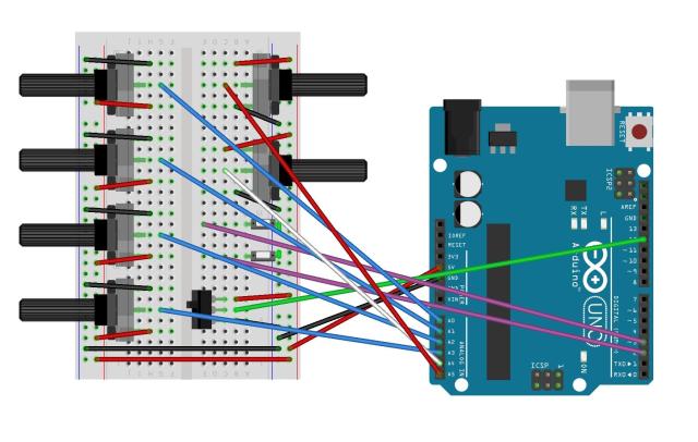
Circuit as Built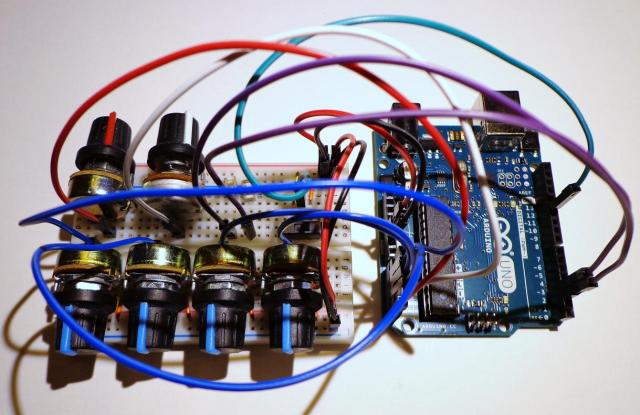
Close Ups Slideshow
Program
/*
  Standard_MIDI_Program for HALF-SIZE BREADBOARD

  This program reads 2 digital switches and 6 ADC sensors.
  It reads an ON/OFF switch connected to pin D12.  It allows
  for HAIRLESS MIDI (software serial connection).

  This program requires no external libraries and is written
  with an emphasis on simplicity, not perfection -- no arrays,
  interrupts, or other more complex code.  Polling of analog
  sensors, as programmed, will create a small time delay at
  that point in execution.  Changes in sensors will not be
  implemented until a full cycle of the loop, dependent on
  the timing of those notes to determine when the changes
  will take effect.  Sometimes all you have is a broken
  clarinet.  That didn't stop Messiaen.

  www.amateurmusicology.com  WEI 1/17/2016

*/

// Create variables to use throughout the program

// Two digital switches connected to pins D2 and D3
int switch1, switch2;

// Six ADC sensors connected to A0 to A6
int note_to_play1, note_to_play2, note_to_play3, note_to_play4;
int time_to_play;
int time_between_notes;

// Temporary variable for use with switches
int sequence_shift;


//  SETUP the Arduino with a baud rate and tell
//  it what to do with various pins

void setup() {
  //  Set MIDI baud rate for HAIRLESS MIDI:
  Serial.begin(115000);
  pinMode(2, INPUT_PULLUP);  // breadboard button input
  pinMode(3, INPUT_PULLUP);  // breadboard button input
  pinMode(12, INPUT);  // On-Off Switch input
}


//  LOOP that will cycle endlessly.

void loop() {
  // Check to see if the ON/OFF switch is on.
  // If so, proceed.  Otherwise, keep checking.
  while (digitalRead(12) == HIGH)
  { //  Collect all sensor data

    //  Because these are INPUT_PULLUP switches,
    //  pressed = LOW or 0 and Not Pressed = HIGH or 1
    switch1 = digitalRead(2);
    switch2 = digitalRead(3);

    // Gather ADC sensor data and map 0 to 1023 to
    // +/- 24 half steps up to middle C (36-60)
    note_to_play1 = map(analogRead(A0), 0, 1023, 36, 60);
    note_to_play2 = map(analogRead(A1), 0, 1023, 36, 60);
    note_to_play3 = map(analogRead(A2), 0, 1023, 36, 60);
    note_to_play4 = map(analogRead(A3), 0, 1023, 36, 60);

    //  5th and 6th ADC sensors mapped to 5 to 500
    time_to_play = map(analogRead(A4), 0, 1023, 5, 500);
    time_between_notes = map(analogRead(A5), 0, 1023, 5, 500);

    // Check switches for desired sequence shift
    sequence_shift = 0;
    if  (switch1 == 0) sequence_shift = 4;
    if  (switch2 == 0) sequence_shift = -3;

    //  Implement the shift
    note_to_play1 = note_to_play1 + sequence_shift;
    note_to_play2 = note_to_play2 + sequence_shift;
    note_to_play3 = note_to_play3 + sequence_shift;
    note_to_play4 = note_to_play4 + sequence_shift;


    // play a note using the function defined below
    noteOn(0x90, note_to_play1, 100);
    delay(time_to_play);
    noteOn(0x90, note_to_play1, 0);
    delay(time_between_notes);

    // play a note using the function defined below
    noteOn(0x90, note_to_play2, 100);
    delay(time_to_play);
    noteOn(0x90, note_to_play2, 0);
    delay(time_between_notes);

    // play a note using the function defined below
    noteOn(0x90, note_to_play3, 100);
    delay(time_to_play);
    noteOn(0x90, note_to_play3, 0);
    delay(time_between_notes);

    // play a note using the function defined below
    noteOn(0x90, note_to_play4, 100);
    delay(time_to_play);
    noteOn(0x90, note_to_play4, 0);
    delay(time_between_notes);

  }

}


/*  noteOn function to play a MIDI note
    COMMAND 0x90 sends NOTE ON on Channel 1.
    PITCH is the note from 0 to 127 with 60 as middle C.
    Keep in mind that some MIDI instruments may not sound
    outside of their normal real acoustic range.
    VELOCITY is how hard the note is struck (from 0 to 127),
    but is often perceived as volume.
    Using 0 for velocity is the same as turning a note OFF,
    so that is often used instead of a note OFF command.
*/

void noteOn(int command, int pitch, int velocity) {
  Serial.write(command);
  Serial.write(pitch);
  Serial.write(velocity);
}
FULL-SIZE Circuit
This video demonstrates how it works. Below that is the circuit digram. Note the inset picture of a MIDI jack as connected to the breadboard. Following the circuit diagram are some pictures of a real version of the circuit as built.
Mathematical Midi for Musical Experiments
Diagram

Circuit as Built
Close Ups Slideshow
Program
/*
  Standard_MIDI_Program for FULL-SIZE BREADBOARD

  The program demonstrates different mathematical operations on
  notes, time, and the order of the serial sequence of notes
  using switches to trigger the operation.  This program reads
  up to 10 digital switches   and 6 ADC sensors.  It reads an
  ON/OFF switch connected to pin D12.

  It allows for both HAIRLESS MIDI (software serial connection)
  and CLASSIC MIDI (hardware connection) through a standard
  5-pin connector with output via the TX pin (D1).  Note that
  the appropriate baud rate (speed) of midi transmission
  should be adjusted in the setup function.

  This program requires no external libraries and is written
  with an emphasis on simplicity, not perfection -- no arrays,
  interrupts, or other more complex code.  Polling of analog
  sensors, as programmed, will create a small time delay at
  that point in execution.  Changes in sensors will not be
  implemented until a full cycle of the loop, dependent on
  the timing of those notes to determine when the changes
  will take effect.  Sometimes all you have is a broken
  clarinet.  That didn't stop Messiaen.

  www.amateurmusicology.com  WEI 1/17/2016

*/

// Create variables to use throughout the program

// Ten digital switches connected to pins D2 to D11
int switch1, switch2, switch3, switch4, switch5, switch6,
    switch7, switch8, switch9, switch10;

// Six ADC sensors connected to A0 to A6
int note_to_play1, note_to_play2, note_to_play3, note_to_play4;
int time_to_play;
int time_between_notes;

// Temporary variables for use with switches
int sequence_shift;
int time_shift1, time_shift2 , time_shift3, time_shift4;


//  SETUP the Arduino with a baud rate and tell
//  it what to do with various pins

void setup() {
  //  Set MIDI baud rate for HAIRLESS MIDI:
  Serial.begin(115000);
  //  If using CLASSIC MIDI:
  //   Serial.begin(31250);

  pinMode(2, INPUT_PULLUP);  // breadboard button input
  pinMode(3, INPUT_PULLUP);  // breadboard button input
  pinMode(4, INPUT_PULLUP);  // breadboard button input
  pinMode(5, INPUT_PULLUP);  // breadboard button input
  pinMode(6, INPUT_PULLUP);  // breadboard button input
  pinMode(7, INPUT_PULLUP);  // breadboard button input
  pinMode(8, INPUT_PULLUP);  // breadboard button input
  pinMode(9, INPUT_PULLUP);  // breadboard button input
  pinMode(10, INPUT_PULLUP);  // breadboard button input
  pinMode(11, INPUT_PULLUP);  // breadboard button input

  pinMode(12, INPUT);  // ON/OFF Switch input

  pinMode(13, OUTPUT);  // Use LED to indicate running
}


//  LOOP that will cycle endlessly.

void loop() {
  // At start, set LED to OFF
  digitalWrite(13, LOW);

  // Check to see if the ON/OFF switch is on.
  // If so, proceed.  Otherwise, keep checking.
  while (digitalRead(12) == HIGH)
  { // Turn LED on to indicate running
    digitalWrite(13, HIGH);
    //  Collect all sensor data

    //  Because these are INPUT_PULLUP switches,
    //  pressed = LOW or 0 and Not Pressed = HIGH or 1
    switch1 = digitalRead(2);
    switch2 = digitalRead(3);
    switch3 = digitalRead(4);
    switch4 = digitalRead(5);
    switch5 = digitalRead(6);
    switch6 = digitalRead(7);
    switch7 = digitalRead(8);
    switch8 = digitalRead(9);
    switch9 = digitalRead(10);
    switch10 = digitalRead(11);

    // Gather ADC sensor data and map 0 to 1023 to
    // 24 half steps up to middle C (36-60)
    note_to_play1 = map(analogRead(A0), 0, 1023, 36, 60);
    note_to_play2 = map(analogRead(A1), 0, 1023, 36, 60);
    note_to_play3 = map(analogRead(A2), 0, 1023, 36, 60);
    note_to_play4 = map(analogRead(A3), 0, 1023, 36, 60);

    //  5th and 6th ADC sensors mapped to 5 to 500
    time_to_play = map(analogRead(A4), 0, 1023, 5, 500);
    time_between_notes = map(analogRead(A5), 0, 1023, 5, 500);


    // SIMPLE SEQUENCE OCTAVE UP OR DOWN

    // Check switches for desired sequence shift
    sequence_shift = 0;
    if  (switch1 == 0) sequence_shift = 12;  // up octave
    if  (switch2 == 0) sequence_shift = -12;  // down octave

    //  Implement the sequence shift
    note_to_play1 = note_to_play1 + sequence_shift;
    note_to_play2 = note_to_play2 + sequence_shift;
    note_to_play3 = note_to_play3 + sequence_shift;
    note_to_play4 = note_to_play4 + sequence_shift;


    // CHANGES TO TIMING OF NOTES

    // Switches 3-5 change the time delays of time_to_play
    // and time_between_notes by using a time_shift multiplier
    // Initial value = 1 which leaves the timing unchanged.
    time_shift1 = 1;
    time_shift2 = 1;
    time_shift3 = 1;
    time_shift4 = 1;

    // If switch3 is pressed, multiply all time delays by 2
    if  (switch3 == 0)
    { time_shift1 = 2;
      time_shift2 = 2;
      time_shift3 = 2;
      time_shift4 = 2;
    }

    // If switch4 is pressed, syncopate the timing
    // Override the value of time_between_notes to ~0 ms
    if  (switch4 == 0)
    { time_shift1 = 3;
      time_shift2 = 1;
      time_shift3 = 3;
      time_shift4 = 1;
      time_between_notes = 0;
    }

    // If switch5 is pressed, lower notes are 4x longer
    if  (switch5 == 0)
    { if (note_to_play1 < 48) time_shift1 = 4;
      if (note_to_play2 < 48) time_shift2 = 4;
      if (note_to_play3 < 48) time_shift3 = 4;
      if (note_to_play4 < 48) time_shift4 = 4;
    }

    // If switch6 is pressed, assign random time_shift
    // between 1 and 4  (resets random each loop)
    // Override the value of time_between_notes to `0 ms
    if  (switch6 == 0)
    { time_shift1 = random(1,4);
      time_shift2 = random(1,4);
      time_shift3 = random(1,4);
      time_shift4 = random(1,4);
      time_between_notes = 0;
    }


    // WHOLE TONE SCALE ONLY

    // If switch7 is pressed, play whole note scale
    // Even only numbers:  C, D, E, Gb, Ab, Bb)
    if (switch7 == 0)
    { if ( (note_to_play1 % 2) != 0)
        note_to_play1 = note_to_play1 + 1;
      if ( (note_to_play2 % 2) != 0)
        note_to_play2 = note_to_play2 + 1;
      if ( (note_to_play3 % 2) != 0)
        note_to_play3 = note_to_play3 + 1;
      if ( (note_to_play4 % 2) != 0)
        note_to_play4 = note_to_play4 + 1;
    }


    // STANDARD SERIAL ROW PROCESSES
    // INVERTED, RETROGRADE, RETROGRADE INVERTED

    // If switch8 is pressed, flip the sequence upside down
    // relative to the first note held constant
    // Serial row INVERTED.
    if (switch8 == 0)
    { int diff1, diff2, diff3;
      diff1 = note_to_play2 - note_to_play1;
      diff2 = note_to_play3 - note_to_play1;
      diff3 = note_to_play4 - note_to_play1;
      note_to_play2 = note_to_play1 - diff1;
      note_to_play3 = note_to_play1 - diff2;
      note_to_play4 = note_to_play1 - diff3;
    }

    // If switch9 is pressed, reverse the order
    // Serial row RETROGRADE
    if (switch9 == 0)
    { int tmp1, tmp2, tmp3, tmp4;
      tmp1 = note_to_play1;
      tmp2 = note_to_play2;
      tmp3 = note_to_play3;
      tmp4 = note_to_play4;

      note_to_play1 = tmp4;
      note_to_play2 = tmp3;
      note_to_play3 = tmp2;
      note_to_play4 = tmp1;
    }

    // If switch10 is pressed, reverse the order
    // Serial row RETROGRADE INVERTED
    if (switch10 == 0)
    { int diff1, diff2, diff3;
      diff1 = note_to_play2 - note_to_play1;
      diff2 = note_to_play3 - note_to_play1;
      diff3 = note_to_play4 - note_to_play1;
      note_to_play2 = note_to_play1 - diff1;
      note_to_play3 = note_to_play1 - diff2;
      note_to_play4 = note_to_play1 - diff3;

      int tmp1, tmp2, tmp3, tmp4;
      tmp1 = note_to_play1;
      tmp2 = note_to_play2;
      tmp3 = note_to_play3;
      tmp4 = note_to_play4;

      note_to_play1 = tmp4;
      note_to_play2 = tmp3;
      note_to_play3 = tmp2;
      note_to_play4 = tmp1;
    }


    // play a note using the function defined below
    noteOn(0x90, note_to_play1, 100);
    delay(time_to_play * time_shift1);
    noteOn(0x90, note_to_play1, 0);
    delay(time_between_notes * time_shift1);

    // play a note using the function defined below
    noteOn(0x90, note_to_play2, 100);
    delay(time_to_play * time_shift2);
    noteOn(0x90, note_to_play2, 0);
    delay(time_between_notes * time_shift2);

    // play a note using the function defined below
    noteOn(0x90, note_to_play3, 100);
    delay(time_to_play * time_shift3);
    noteOn(0x90, note_to_play3, 0);
    delay(time_between_notes * time_shift3);

    // play a note using the function defined below
    noteOn(0x90, note_to_play4, 100);
    delay(time_to_play * time_shift4);
    noteOn(0x90, note_to_play4, 0);
    delay(time_between_notes * time_shift4);

  }

}


/*  noteOn function to play a MIDI note
    COMMAND 0x90 sends NOTE ON on Channel 1.
    PITCH is the note from 0 to 127 with 60 as middle C.
    Keep in mind that some MIDI instruments may not sound
    outside of their normal real acoustic range.
    VELOCITY is how hard the note is struck (from 0 to 127),
    but is often perceived as volume.
    Using 0 for velocity is the same as turning a note OFF,
    so that is often used instead of a note OFF command.
*/

void noteOn(int command, int pitch, int velocity) {
  Serial.write(command);
  Serial.write(pitch);
  Serial.write(velocity);
}
BREADBOARD / CUTTING BOARD
Circuits circa 1970, woodgrain all the way.
WEI 2016

You must be logged in to post a comment.