

“Rule #17: If it sounds good and doesn’t smoke, don’t worry if you don’t understand it.” ~ Nicholas Collins, Handmade Electronic Music: The Art of Hardware Hacking, Second Edition, Routledge, 2009, p. 144.
Collins describes it as the “world’s simplest oscillator” and that must be true. One integrated circuit, a capacitor, a resistor, a battery, and a couple of wires. That’s it. There are countless examples of this circuit available on the Internet, but Collins’ Handmade Electronic Music book provides a step-by-step guide for many such circuits. Collins has posted an earlier draft of the manual here.
This post demonstrates an oscillator built like the one described in Collins’ book. These circuits use the CD40106BE chip, a Hex Inverting Trigger CMOS chip.

This post describes the basic circuit and three different ways to control the pitch. The first two methods are common approaches: a potentiometer and a photocell, both of which allow you to control the pitch by changing the resistance. The third method is a new take on an old approach. Many experimenters have used pencil etchings to create a graphite strip that acts like a resistor. This approach takes a standard #2 pencil and turns that into a musical stylus – like a stylophone that draws pictures of pitch. To skip all this backstory and just see the video, click here.
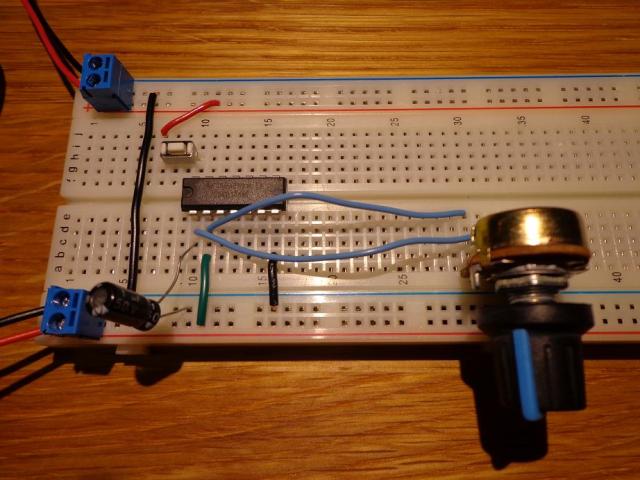
For each version, there is a Fritzing diagram and some pictures of the circuit as built. These are no-solder versions of the circuit to make building this as easy as possible. Terminal blocks are used to connect the battery and piezo speaker to the breadboard. Note the use of the RED bus for the red wire of the piezo speaker is NOT the same as the RED bus for the battery. A 10K breadboard-friendly pot is used.
The resistors/capacitors here are not the same as in Collins’ book, mostly to accommodate the breadboard-friendly pot and photocell values. Values are noted in the diagrams. The first two versions (pot and photocell) use a button from the battery to the power pin of the CD40106BE to turn the CD40106BE on/off when the button is pressed. That may not be the most appropriate design, but it certainly eliminates the possibility of accidentally draining the battery when you are just getting started. The musical stylus method doesn’t require a switch, the pencil-to-paper completes the circuit.
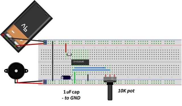
BASIC Circuit with Potentiometer
Here is the basic circuit with only slight modifications from the original Collins’ design.

BASIC Circuit with Photocell
Here is the basic circuit with a photocell instead of a potentiometer. This is a 10K photocell so it simply relaces the potentiometer.

An additonal resistor in the series can be used to restrict the range of the pitch, especially useful with the photocell. This is a 4.7K resistor.

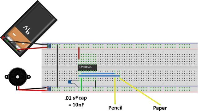
Musical Stylus Circuit
This is the musical stylus. Graphite strips drawn with a pencil have been commonly used in electronics experiments to create cheap, useful variable resistors. But this approach takes that method one step further. Here is a video of the stylus in action:
First, you need to prepare the pencil. Using a 1/32 inch dremel drill bit, drill a hole through the middle of the pencil. This example uses the #2 on the pencil as a target, high enough to keep the wire out of our way when we use the stylus. Cut about 18 inches of #22AWG wire and strip about an inch from one end. Push that end through the hole in the pencil, bend over the additional wire, and tape the wire securely to the pencil just to hold it in place. This is the stylus.


Assemble the standard circuit as before, but remove the button connecting the battery to the CD40106BE. Connect the chip directly to the battery. Cut a second piece of wire about 6 inches long and strip an inch from one end of that. That will connect the circuit to the paper where we will draw the music. Note as well that you should use a capacitor with a significantly lower capacitance — here 10nF (aka .01uF).


Last Notes / Next Notes
For more on the history of the early days of Experimental Electronic Music, see Collins’ handwritten notebooks from his Introduction to Electronic Music class with Alvin Lucier (an historical record that ensures Collins’ place as the Herodotus of Hardware Hacking). For a look at ways in which avant garde composers used and misused electronics, see the kinds of magical circuity developed by David Tudor in his work with John Cage and others. For a very modern spin on these circuits and other musical designs, see the excellent Logic Noise series on Hackaday by Elliot Williams.
Best of all, unless you wire the battery to the chip backwards, it is hard to accidentally destroy this simple circuit. Resistors and capacitors can be replaced, compounded using multiple connections on the chip, and summed and subtracted in various combinations. There are no rules, except perhaps the rules Sister Corita Kent described in her famous Rules for Students and Teachers:
RULE FOUR: “Consider everything an experiment.”
RULE SIX: “Nothing is a mistake. There’s no win and no fail, there’s only make.”
WEI 2016

You must be logged in to post a comment.